Commissioning is not the end of installation. It’s the proof that installation was done correctly. Every rooftop solar kit that gets switched on without a documented commissioning test sequence is a system whose baseline performance is unknown, and whose first fault will be diagnosed blind, without a reference point to compare against.
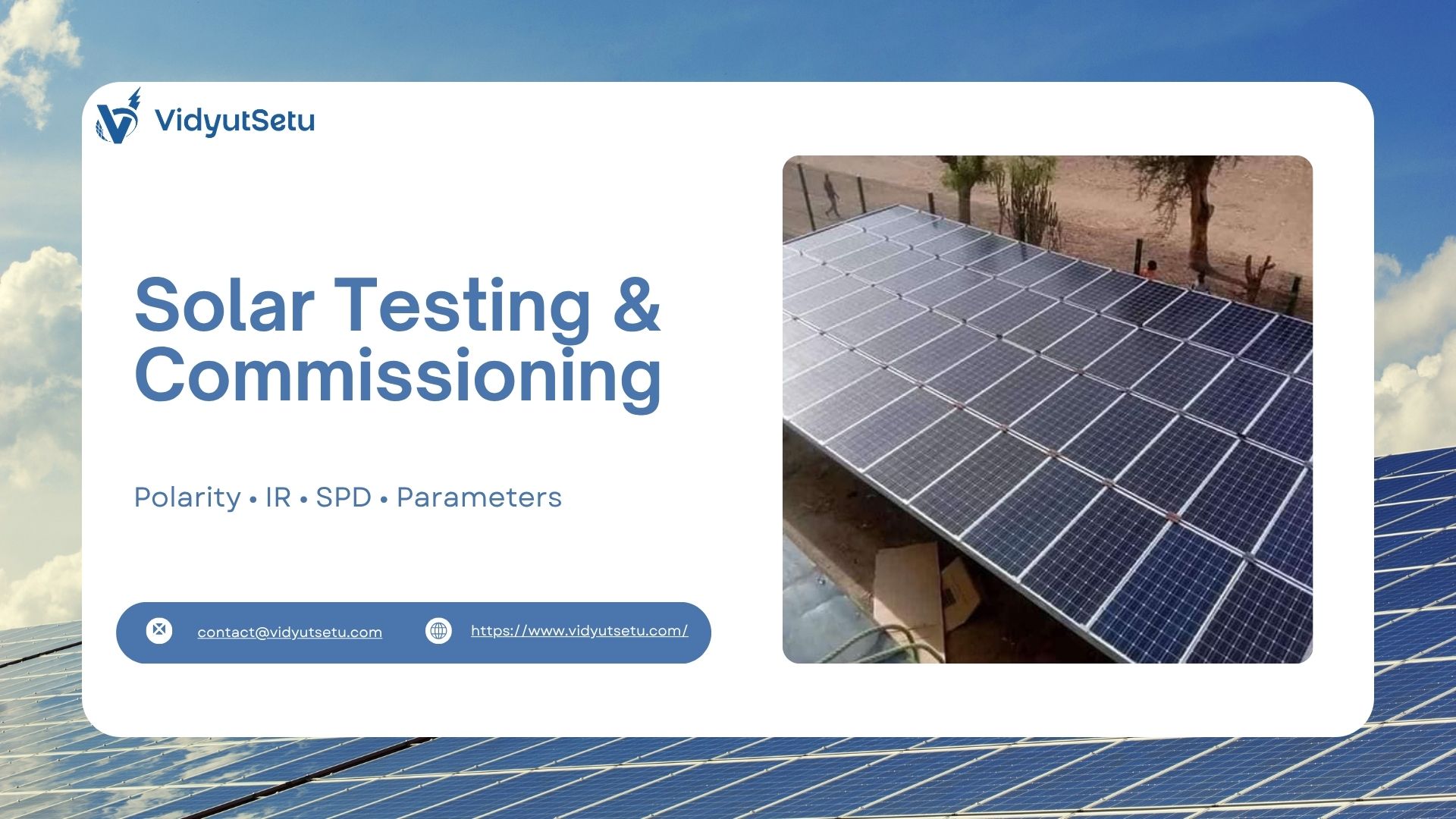
A complete commissioning test sequence for a solar kit covers six verification areas: DC polarity and open-circuit voltage, insulation resistance (IR) testing at 500V or 1000V DC, earth resistance measurement below 5 ohms, SPD cartridge health check, inverter parameter verification against site-specific settings, and net meter readiness confirmation with DISCOM.
Skipping any one of these is not time-saving. It’s risk transfer, from the installer to the client, and eventually back to you.
The Commissioning Conversation Nobody Has
Here’s how most residential solar kit handovers go in India.
The installation team completes cable runs and module mounting by 4 PM. The inverter gets switched on. AC output light turns green. Someone takes a photo for WhatsApp. The client signs the job completion form.
What didn’t happen: polarity verification before energisation. Insulation resistance measurement on the DC strings. Earth resistance confirmation with an instrument. SPD cartridge visual check. Inverter parameter review against site irradiance and string configuration. DISCOM net meter application status.
Six tests. Zero performed. One green light as a proxy for all of them.
This is how systems get commissioned that shouldn’t be. And it’s how faults that should have been caught in 20 minutes on Day 1 become diagnostic problems that take 4 hours to trace on Day 180.
Test 1: DC Polarity and Open-Circuit Voltage
Before any DC connection reaches the inverter, verify polarity at every string output using a multimeter. Positive terminal reads positive. Negative reads negative. This sounds obvious. It gets wrong more often than the industry admits, particularly in multi-string arrays where strings are landed in a combiner box by different technicians.
Simultaneously, measure and record Voc (open-circuit voltage) for each string.
A string of 9 panels at 400Wp with individual Voc of 37.5V should read approximately 330V to 338V at the combiner output at morning commissioning (when cell temperature is near ambient). If any string reads more than 5% below the theoretical Voc, one panel in that string is either shaded, bypassed, or has a failed cell string.
This measurement takes 3 minutes per string. It’s the only test that catches wiring errors before the inverter absorbs them.
Test 2: Insulation Resistance (IR) Testing
IR testing measures the resistance between the DC conductor (positive or negative) and the system earth. A healthy, newly installed solar kit should show IR values above 1 MΩ per IEC 62446-1 requirements, in practice, new systems typically read 100 MΩ or higher.
The test is performed with the inverter DC isolator open, using a dedicated insulation resistance tester at 500V DC for systems up to 500V string voltage, or 1000V DC for higher-voltage strings common in commercial ongrid configurations.
Test both positive-to-earth and negative-to-earth independently. Both values must pass.
A low IR reading, below 1 MΩ, means insulation damage somewhere in the DC wiring, a pinched cable under a mounting clamp, a failed MC4 connector, or water ingress at a junction box. Finding this before energisation is a 20-minute investigation. Finding it after energisation, when the inverter’s GFDI trips on a humid monsoon morning six months later, is a full-day service event.
The instrument matters. A multimeter cannot perform an IR test. A clamp meter cannot perform an IR test. A dedicated insulation tester, calibrated and capable of output at the correct test voltage, is the only valid instrument.
Test 3: Earth Resistance Measurement
The solar earthing kit is verified, not assumed, with a calibrated earth resistance tester using the 3-point fall-of-potential method. The target: below 5 ohms for residential solar kit installations, below 1 ohm for commercial ongrid systems above 10kW.
Record the measured value, the instrument used, the date, and the soil moisture conditions at time of measurement. This record is the baseline. Every future IR fault, GFDI trip, and unexplained inverter shutdown will be compared against it.
If the measured value exceeds the target at commissioning, after installation of the copper-bonded rod and GEM-enhanced backfill, the commissioning sequence stops. The earthing system is remediated first. The inverter does not get energised.
This is not conservative. This is the correct sequence.
Test 4: SPD Health Check
The surge protection device installed at the DC input of the ongrid solar inverters has a visual status indicator, typically a green/red window or LED. Green means the SPD varistor element is intact and functional. Red or absent indication means the varistor has been consumed, either by a previous transient event or by manufacturing defect.
An SPD that reads red on commissioning Day 1 was either damaged in transit or was already at end-of-life before installation. It provides zero protection.
The visual check takes 30 seconds. It also verifies that the SPD was actually installed, a fact that cannot be confirmed from the inverter display or from outside the DC enclosure.
For commercial ongrid installations with Type I+II cascaded SPD configuration, check both the combiner-box-level device and the inverter-input device independently. Both must show healthy status before system energisation.
Test 5: Inverter Parameter Verification
Every ongrid solar inverter ships with default parameters that are not necessarily correct for your specific installation. Before the first grid connection, verify and record:
| Parameter | What to Check |
| Grid voltage limits | Set per DISCOM tolerance band — typically 180V to 264V for Maharashtra |
| Grid frequency limits | 47.5 Hz to 51.5 Hz per CEA 2019 norms |
| Anti-islanding response time | Confirm enabled, typically < 2 seconds detection |
| MPPT voltage window | Matches string Voc and Vmp at site irradiance |
| Export limitation setting | Required by some DISCOMs for residential net metering |
| Reactive power settings | Q(U) or fixed PF as specified by DISCOM |
For ongrid solar inverters configurations that include a data logger or monitoring gateway, verify communication between the inverter and the monitoring platform at commissioning, not three weeks later when the client asks why their app shows no data.
The parameter review takes 15 minutes. It’s the difference between a system that DISCOM approves on first inspection and one that comes back flagged for grid protection non-compliance.
Test 6: Net Meter Readiness
Net meter readiness is not a technical test. It’s a documentation and application status check. But it’s part of commissioning because it determines whether the system can legally export to the grid, and therefore whether the client’s subsidy disbursement clock has started.
Before handover, confirm:
- Net meter application submitted to DISCOM with correct installation details
- Bidirectional meter delivery timeline confirmed with DISCOM
- Inverter export limitation set correctly for interim operation period (many DISCOMs require zero export until net meter is installed)
- Client briefed on interim operation mode and what the inverter display will show
A commercial ongrid project handed over without net meter application status confirmation is a project whose financial case to the client is incomplete. They installed for net metering benefits. Until the meter is in place, they’re not receiving them.
The Commissioning Record That Protects Everyone
Every test result gets documented. One commissioning report per system, dated and signed by the commissioning technician, containing:
- String Voc measurements per string
- IR test values (positive-to-earth, negative-to-earth) with instrument ID
- Earth resistance measured value with method and conditions
- SPD status (pass/fail) at commissioning
- Inverter parameter settings as configured
- Net meter application reference number and submission date
This document is handed to the client at project close. It’s also retained in the installer’s project file.
When a system develops a fault in year 3, this record tells you what was true on Day 1. That’s the baseline you need to diagnose what changed. Without it, every fault investigation starts from zero.
Why VidyutSetu Commissions Differently
At VidyutSetu, commissioning is a scheduled event, not an improvised conclusion to installation day.
Every solar kit we install, residential or commercial ongrid, goes through a documented 6-test commissioning sequence with recorded results. Our solar earthing kit verification includes instrument-measured earth resistance with date and conditions. Our ongrid solar inverters are parameter-verified against the site-specific DISCOM tolerance band before first grid connection. Our clients receive a commissioning report at handover, not just a warranty card.
We do this because we’ve seen what happens when commissioning is treated as a formality. We’ve traced the faults. We’ve done the return visits. We’ve replaced the inverters that a correct IR test would have protected.
If your current installer’s commissioning process ends when the green light comes on, ask for the commissioning report. If there isn’t one, you don’t yet know whether your system was installed correctly. You only know it was installed.